DBD Plasma Actuator
The dielectric barrier discharge (DBD) plasma actuator is extremely fast response, light weight, flexibility to be installed and the low power consumption.
The dielectric barrier discharge (DBD) plasma actuator has gained great popularity in active flow control in the past decade because of its extremely fast response, light weight, flexibility to be installed and the low power consumption. It has been widely applied for drag reduction, separation control, lift enhancement, noise control and maneuvering.

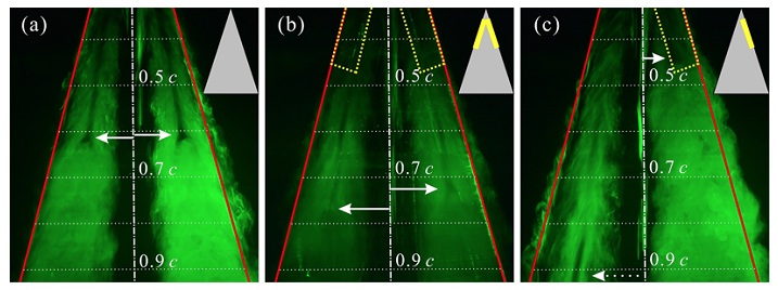
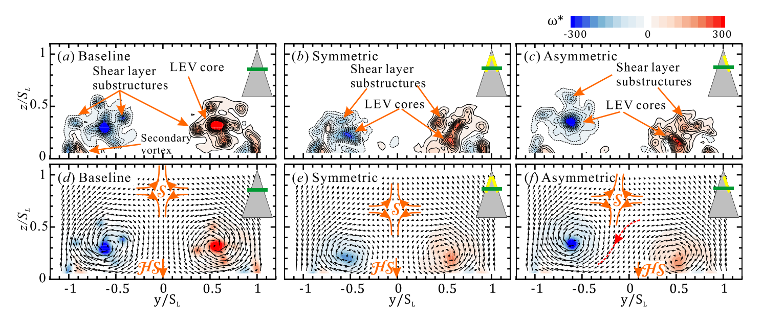
1. Applications for flow control over a delta wing
2. Flow control of a D-shaped bluff wake
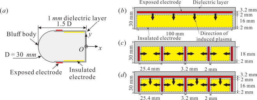
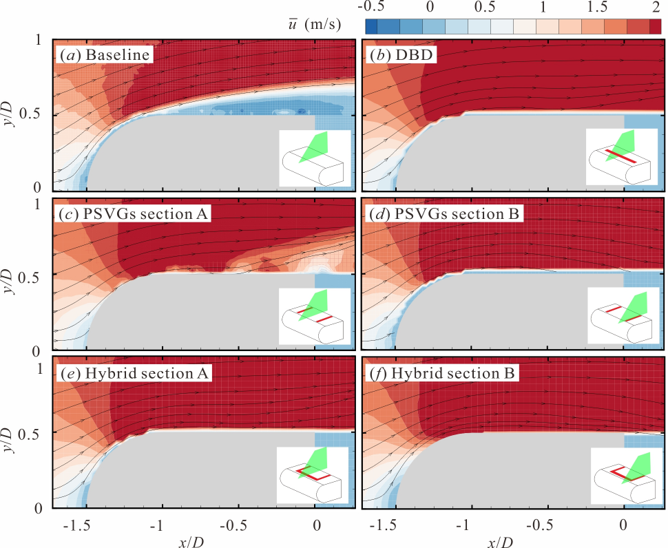
The stable controlled vortex shedding system can reduce the effect of the natural frequency of the bending stiffness-dominated cylinder structure system, thus avoiding the occurrence of resonance in advance. The reduction in drag and lateral lift oscillation are studied by mapping the changes in force coefficients and fluctuations as a function of Reynolds number. A comparison of these plasma actuators shows that the hybrid actuator achieves best drag reduction, suppression of lift oscillation, and Kármán vortex shedding in the wake at low speed, because three-dimensional flow structures are generated on the surface of the bluff body that consequently enhance the mixing. The results suggest that PSVGs and ameliorative actuators are promising for wake flow control in bluff bodies at low speeds.
3. Control of supersonic compression corner flow
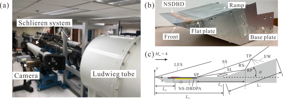
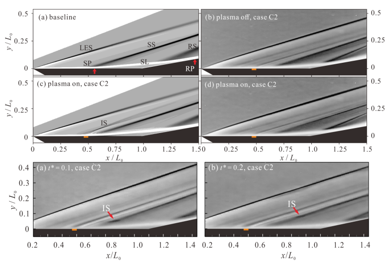
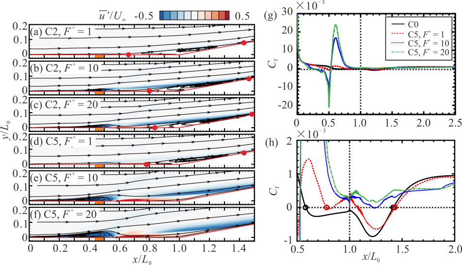
The results indicate that the discharge induces a pressure rise and leads to misalignment between the pressure gradient and density gradient in the residual heat region. Because of the interaction between the supersonic freestream and the actuation-induced shock/ compression flow, convection, compressibility of the fluid element, and baroclinicity of the residual heat region collectively lead to the formation of an induced spanwise vortex, which in turn enables momentum migration. The induced vortex disrupts the initial flow structures and entrains high-energy fluid from the main flow into the boundary layer, promoting momentum mixing between the main flow and the separated flow, which increases the energy of the boundary layer to resist the adverse pressure gradient. The time-averaged flow structures imply that it is possible to totally eliminate the flow separation near the supersonic compression corner. For aerodynamics on the surface, the normal force produces a pitching moment that can be potentially utilized to control the body’s orientation and trajectory. Additionally, total drag on the surface can be reduced by 5 %. This suggests that choosing the most appropriate position based on its local fluid characteristics can strongly increase the control effectiveness.
4. Thermal effects of DBD plasma actuators
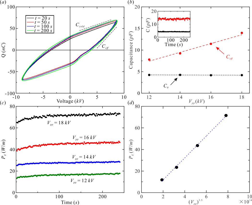
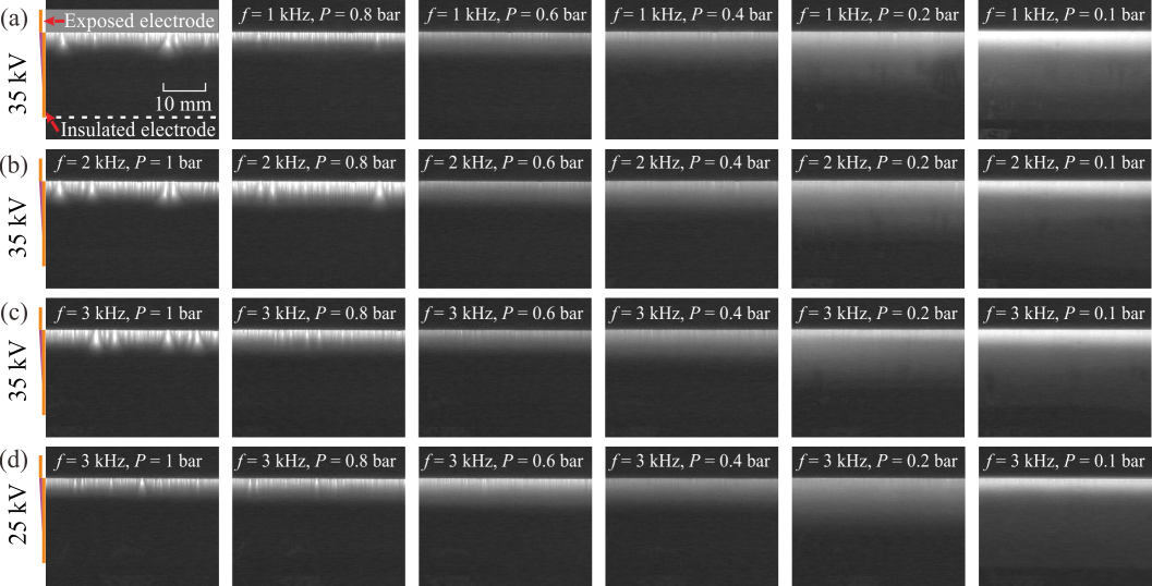
Different discharge modes and discharge parameters exhibit markedly different thermal performances. Also, the Schlieren technique and the pressure sensor are used to visualize the induced shock wave, estimate the thermal expansion region, and measure the overpressure strength. The results of the overpressure strength at different air pressures are similar to the thermal features, which highlights the strong influence of the discharge mode on the thermal effect of NSDBD plasma actuators.
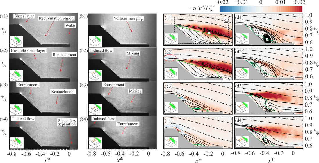
5. Flow control of a notch-back Ahmed body
The induced flow upstream of the slant enhances the momentum in the boundary layer, marginally reducing the separation and drag. However, the activation located at the leading edge of the slant almost completely suppresses the central large-scale separation, facilitating the reattachment of the separated shear layer to the deck surface. The reattachment leads to a consequential intensification of the C-pillar vortices, causing a deviation in their trajectories outward and an increase in drag. This suggests that the PSVG is a promising technique for automobile wake control. The activation location leads to different flow structures, implying various control mechanisms. For further drag reduction, both suppressing wake separation and mitigating longitudinal vorticity should be considered.
